Marko Dimitrijevic, Applications Engineer, International Components Corp.
Lithium-ion (Li-Ion) batteries have increasingly become the enabler of modern portable technology products ranging from laptop computers, communications handsets and medical equipment. Contemporary Li-Ion cells offer energy densities that are significantly higher than legacy battery chemistries such as nickel cadmium (NiCd), nickel metal hydride (NiMh) and lead acid (LA). Smaller form factor and weight of Li-Ion cells enable the development of compact, feature-rich products with long run times.
Although the advantages of Li-Ion cells make them particularly attractive, they must be used in conjunction with advanced protection circuits. Development of advanced Li-Ion battery packs requires expertise and experience in order to balance system load demands with reliability and safety.
Due to their volatile nature, Li-Ion cells must be protected by additional layers of safety. When developing a safety circuit, design engineers should consider the required levels of protection, redundancy, compensation for excessive load transients, protection settings and special application requirements.
Levels of Protection
Before proceeding, it should be noted that there is a significant difference between a cell and a battery pack. A cell is considered the basic component that stores and releases charge. NiCd, NiMh and LA cells can be used without additional levels of safety as they are generally non-volatile. Li-Ion cells, however, need safety components and circuits to monitor and manage the charge/discharge cycles and prevent inadvertent application and mishandling. Only after those circuits are added could such systems be considered batteries. That is why development of Li-Ion battery packs is often much more elaborate than construction and assembly of standard batteries.
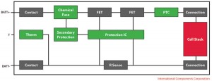
One level of protection to an advanced Li-Ion battery pack is the PTC, or positive thermal coefficient device. It reacts to high current discharge levels to increase output impedance. The increased impedance controls output current and the PTC can disconnect the output path if the discharge levels exceed safe limits. Most contemporary high energy cylindrical Li-Ion cells incorporate a PTC, eliminating the need, cost and complexity of adding such a component.
Another more active level is often the charge/discharge monitoring cutoff circuit. Controlled by the protection IC, this circuit monitors charge/discharge levels and activates/deactivates the relative transistors (switches) to allow or inhibit current flow. This works in combination with the PTC to prevent unwanted side effects of overload or short circuits. Cutoff circuits often utilize a thermal sensor to monitor individual cell temperatures and also trigger accordingly.
Individual cell monitoring circuits provide an additional level of protection. These circuits respond to cell imbalance conditions in packs with multiple cells connected in series. The absence of individual cell monitoring circuits can lead to cell imbalance, which can result in uneven or excessive charging and discharging of individual cells. If any of the cells connected in series exhibits levels significantly different from other series cells, the cell monitoring circuit triggers the cutoff process.
 Chemical fuses are also utilized to provide permanent circuit interruption, if it ever becomes necessary. These fuses are controlled by the cell monitoring and cutoff circuits. If activated, the fuse permanently disables the battery pack and prevents current flow. Although it may appear extreme, such actions are sometimes necessary if the battery is subjected to over-charge, over-current or deep discharge conditions.
The four levels of safety indicated above form the fundamental protection system for many Li-Ion battery packs. Medical devices often require all four levels in order to provide redundant measures of protection. In some cases a PTC-only approach could be considered adequate, but medical devices should incorporate all available forms of protection.
Potential Drawbacks of Excessive Protection
There is a potential drawback to having too much protection and it should be noted that all safety functions are designed to operate only when the battery is subjected to an abuse condition (over-charge, over-current or deep discharge). In applications with high transient or instantaneous loads the design challenge is developing a circuit that accurately determines the difference between a short circuit condition (over-current) and normal operation of the equipment. Furthermore, inadvertent or nuisance operation of safety functions could become a safety hazard if the medical device is vital to a life sustaining function. This places the responsibility on battery pack development engineers to design a safe, yet reliable pack.
Determining Firmware Settings
In certain situations a battery pack may face momentary transient loads that exceed optimal levels. Although excessive loads are usually detrimental to Li-Ion cells, their effects can be mitigated by proper load analysis. If overlooked, these brief load spikes can impact the reliability of the battery pack by causing inadvertent activation of protection circuitry. Design engineers must be able to balance safety, reliability and robustness when developing an advanced battery pack.
 No matter how accurate the models are and how much real world simulation testing is performed, it is often not possible to accurately model peak transient loads. This is especially true in motor-driven devices. PTC protection is mostly benign and will not react quickly enough to short overloads, but active protection circuits must be developed with appropriate reaction time and hysteresis.
Protection circuit reaction time is determined by parameter settings in the control IC firmware. Design engineers have options of not only setting the critical thresholds, but also time constants for reaction time. A protection circuit could be made to react faster or slower to a transient event by varying the time constants. It should be noted that transient events do not always have to be excessively high transient spikes. Momentary loads can induce temporary cell voltage dips to below minimal values. Although this is not desirable, it is permissible for brief periods.
In addition to thresholds, engineers can modify the firmware settings to control the hysteresis of a particular circuit. Hysteresis could be viewed as the desired lag between an initial trigger event and the point at which the circuit resets. By adjusting the protection threshold hysteresis appropriately, designers can ensure that a battery pack will not enter an undesirable oscillation mode between a fault condition and subsequent relaxation.
The Effect of EMI
It should also be noted that active protection circuits must be resilient to electromagnetic interference, or EMI. Electromagnetic energy can induce a voltage potential across key protection circuit sense lines or components, inducing a fault condition. This is especially the case in products that are likely to be used near the sources of significant EMI, such as MRI and X-ray machines. General protection circuits are self resetting, but chemical fuse applications should especially be evaluated in such cases. Inadvertent triggering could render the pack permanently disabled.
Conclusion
Li-Ion technology is at the forefront of advanced battery design. Device manufactures are transitioning from legacy chemistries to take advantage of the many benefits Li-Ion has to offer. Additional hardware and software must be applied to Li-Ion cells to ensure safe and reliable battery pack operation. This article outlined the various levels of protection, reviewed firmware setting options and discussed EMI considerations, all necessary elements for an advanced Li-Ion battery pack design.
Based on the complexity of the today’s battery pack design, OEMs will find it advantageous to partner with an expert in battery pack development. Companies such as International Components Corp. (ICC) provide device makers with state of the art battery pack designs that meets today’s design challenges.
Marko Dimitrijevic has a B.S. degree in Electrical Engineering and an M.S.C. in Engineering Management along with 11 years experience developing Base Radio Switch Mode Power Supply hardware, mobile device battery management, Lithium-ion battery chargers and protection circuitry. Marko currently works as an applications engineer at International Components Corp.
Contact International Components Corp. at www.iccus.com.
This article was printed in the November/December 2010 issue of Battery Power magazine.


