Loic Moreau, Business Segment Manager, LEM
The infrastructure that underpins contemporary society must operate with very high reliability. In contrast to the advanced technology deployed in data storage centers, Internet server farms and communications central offices, most of them rely for near-100 percent “up-time”, or system-availability, on a very mature technology; the lead-acid battery. It is standard practice to provide such critical nodes, and many other essential services, with back-up power. The first layer of that back-up is usually an inverter that draws on banks of valve-regulated lead-acid (VRLA) cells, or the closely-related sealed gel-cell types.
This venerable technology continues in widespread use for a variety of reasons including that the cells are economical, and offer excellent reliability. Excellent, but not perfect. VRLA cells do have a finite life, a design life of 12 years is common, and in normal use in critical-system standby power they are routinely replaced on timed basis. Failures can, and do, still occur.
In a typical standby supply the cells do exactly as the name implies, they are held at full charge awaiting failure of the primary supply. This is achieved by maintaining a small, continuous “float” charge. If the float charge current is below a certain limit, the gases produce by electrolysis within the cell will recombine. In this condition, cells can be vulnerable to damage if the float-charge voltage is even a little higher than the standard value of 2.27 V per cell. A small overvoltage will cause the electrolyte to produce more gas than the recombination chemistry can cope with, and this will escape through the valve. Excessive cell temperatures, even with correct charging voltage, will also lead to loss of electrolyte.
Other failure modes include early sulphation, poor connection between the posts and the grids, poor connection between the grids and the plates, stratification of electrolyte and accelerated grid corrosion. An infrequent, but catastrophic, mode of failure is thermal runaway, which is peculiar to VRLA and Gel batteries and can result in fire or explosion. The only way to detect its onset is to monitor the internal cell temperature.
It is recognized that simply monitoring the cell voltage gives very little information about declining capacity of a lead-acid cell. A failing cell will frequently present nominal voltage until it is called on to deliver significant current, when it will exhibit severely reduced capacity with premature collapse of its terminal voltage. Establishing battery condition by measuring electrolyte specific gravity is not possible with the sealed VRLA or gel construction; conventionally, the only way to verify capacity has been to discharge the complete battery under controlled conditions, requiring it to be taken out of service. Deep discharge also reduces the life of lead-acid cells. In an installation that regularly discharge-tests its batteries, and in which the primary power supply has high reliability, the test regime will be the dominant factor in determining battery service life.
Newer, non-intrusive electronic methods of continuous monitoring can detect impending failures in individual cells, saving cost while maintaining full system availability. Early versions of such systems typically measured parameters such as cell or monobloc (the battery-industry term for multiple cells in a single case) voltage, despite the known limitations, plus charge/discharge current and ambient temperature. Some systems attempt, with varying degrees of success, to measure or infer the cells’ internal resistances.
LEM’s Sentinel system pioneered the transition from reliance on simple analogue measurements of basic parameters, and is now in its third generation. It uses a combination of analogue and digital techniques implemented in a single, custom-designed, SoC (system on chip) integrated circuit. This device, deployed in a module that measures terminal voltage, internal cell temperature and internal impedance, is a key element in the design of a system that can deliver accurate measurements within a budget that is affordable for the majority of standby system configurations.

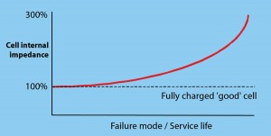
Cell temperatures, and/or internal resistance values, that increase in an exponential manner (Figure 1) are indicative of impending failure, and a data logging system that monitors trends in the data over time will, potentially, identify an impending failure. Each Sentinel III module has an external temperature measurement probe or patch, that is applied directly to the case of the cell or battery, to give the most accurate possible tracking of cell temperature.
An established technique makes an assessment of internal resistance while the cell is in service and on-charge. Exact implementations vary, but typically, a small AC voltage is superimposed on the DC of the float charge, measuring the AC voltage and current yields the internal resistance. The method has limitations, partly to do with the very shape of the exponential curve. A cell that is about to fail can be well along the path to failure before the data logger identifies the trend. Conversely, by the time the problem is spotted, the cell may only be a short time from complete failure.
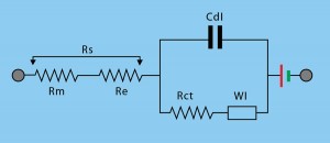
LEM, in association with academic partners, has implemented a much more sophisticated algorithm that detects deteriorating cell performance at a much earlier stage. The result is an extremely dependable test method, which penetrates well into the cell’s energy layer, to ensure the highest possible degree of reliability. It is based on the so-called Randles

equivalent circuit, which represents an electrochemical cell as a network of electrical elements, each of which is related to a physical aspect of the cell’s construction. (See Figure 2)
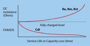
Figure 3 shows the progression of the parameters over the life of a cell. The same characteristics are also demonstrated during a discharge, or loss of capacity. All of the resistance aspects of the equivalent circuit follow a similar curve; they do not change greatly during the early stages of failure, or of capacity loss. If resistance is used as the main indicator of the state of health of a cell, it will not give any significant indication until the capacity loss is greater than 25 to 30 percent. Since the industry standard is to replace batteries that fall below 80 percent of specified performance, it is clear that possible failure must be identified far earlier.
There is, however, one parameter in the Randles equivalent circuit that does change in the early stages of cell failure (except purely metallic corrosion, which will be revealed by an increase in the parameter Rm), and that is Cdl, the double layer
capacitance. Its behavior is indicated in the lower curve in Figure 3; again, the shape of the curve is similar for a healthy cell during normal discharge, or a failing cell that is supposedly fully charged.
The Monitoring Technique
A detailed description of the technique is beyond the scope of this article, but it can be summarized as follows.
The test signal is applied on a cell-by-cell basis, with no requirement to drive high currents through complete blocs or batteries, and no disturbance of DC connections to external systems. The original algorithms were developed using a bipolar test signal, but unipolar signals proved to be more reliable. However, unipolar signals experienced DC drift during the test. Simply removing this trend does not preserve the characteristics of the data set necessary for correct parametric estimation. By rearranging the varying frequency signal pulses that comprise the test signal, in a frequency sweep, the cell voltage response can be made to follow a predetermined curve.

Once the underlying drift curve becomes uniform, firmware algorithms can be designed to model the drift and remove it, resulting in a mean zero voltage data set suitable for direct input to the Sentinel algorithms. This method can reduce drift errors to less than 0.1 percent without causing significant distortion of the data set. Algorithms can then be applied to the measured waveforms, and the equivalent circuit parameters can then be derived with a high degree of accuracy.
Much of the measurement functionality and algorithmic processing has been integrated into a single integrated circuit (system-on-chip, or SoC). Sentinel modules can measure at an individual cell level, or at monobloc level (2 V to 12 V). Up to 250 measurement points, implemented in modular form, can report via a proprietary data bus to a battery data logger, the S-Box. In a large battery installation, several such streams of data can be combined and made available to a variety of local or remote upstream supervisory systems via standard buses or an Internet connection, using a Web server that is integrated in the S-Box.
Having had the measurement SoC determine every cell’s real condition, detecting impending failures is not the only benefit that a sophisticated monitoring architecture can provide; several other features and services can be programed.
For example, the cells of a battery often have differing internal impedances. Over time, this can cause problems. The SoC intelligent control system allows such cells to be quickly detected, and a system, known as terminal voltage optimization, can divert the float current around the cell that cannot tolerate further charging.
Active Charge Management for Extended Life: The float current in VRLA cells is higher than that of flooded types, for the same terminal voltage. This can accelerate positive plate corrosion and reduce the useful life of the cell by up to 30 percent. Removing the float charge for a proportion of service life can reduce this effect. A useful side effect of life cycling is its ability to reduce the possibility of thermal runaway.
A cell-mounted module can also provide a lifetime log of terminal voltage and temperature to help manufacturers and users.
Exhaustive Discharge Protection: It is normal in charger/UPS systems, and even battery monitors, to preserve the battery by terminating a discharge based on the average cell voltage. However, weaker cells can be of a much lower terminal voltage than the battery average and may be exhaustively discharged well before the battery has reached its termination voltage. This can damage these cells permanently. A highly accurate, dynamic ‘Time To Run’ algorithm has been developed to give warning if any individual cell is approaching exhaustion.
Monitoring of standby battery parameters must be as comprehensive as possible, to produce results that most accurately represent the state of the battery. This is not only a technological issue, but an economic one. Avoiding in-service cell failures is essential, but prematurely replacing cells that are not approaching end-of-life is expensive. In addition to voltage, impedance and discharge performance per cell, LEM monitors internal cell temperature as standard. It is also developing a fluxgate-technology float-charge transducer capable of better than 10 mA resolution, with little or no temperature drift and virtually no remanence after a high current discharge, that will further improve measurement fidelity. Advances such as these can change the role of the battery monitor from being an expensive addition, to that of a cost-effective integral life management system.
Loic Moreau is Business Segment manager, New Business for LEM, responsible for driving the strategic approach marketing within the company. He also created and manages the new Energy & Automation Division, which develops transducers that integrate additional electronics to offer added value and increased functionality such as the Sentinel for monitoring standby batteries and Wi-LEM for wireless local energy monitoring.
Contact LEM at www.lem.com.
This article was printed in the September/October 2010 issue of Battery Power magazine.


